 Enough theory. Let’s get our delivery network on the road. Rather than look at the code in this episode (boring), let’s jump straight in and get our nodes chatting. Time enough to see how the code works later.
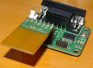
The packet demo is designed to run on the Sparkfun Terminal Development Nodes (TDNs), which are a very handy piece of gear for testing this all out. They have an RS232 connection on one end, a socket for the nRF2401a / nRF24L01 module on the other and a 16f88 in the middle plus a few leds, which help us know a little of what’s going on. Of course you can run this demo on a breadboard with an nRF module or if you’re feeling adventurous, write some code to support a different RF module all together. There are a bunch out there, do send your code in to include in the library if you get something working. I’m pretty interested in seeing some of the CC2500-based modules going, which are similar in nature to the Nordic ones (but are cheaper and have carrier detection – hooray!) or the modules from the fabulous Futurlec (even cheaper, carrier detection but fascinatingly obscure datasheets – fun!).
For the purpose of this experiment, however, I’ll assume you’ve got a couple of SparkFun TDN (Terminal Development Node) and Nordic modules and a couple of serial ports (USB to serial converters will work fine) or a couple of computers with a serial port each.
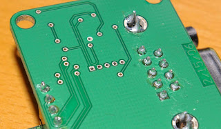
 The first step, naturally, is to get Boostbloader downloaded onto the 16f88 on each TDN. You’ll need the little mini adapter from SparkFun in order to reach their mini-ICSP connector. See the 5 holes together in the middle of the board? That's the ICSP "socket". Make sure you work out which way round the connector goes – pin 1 is designated by the square pad. The datasheet shows how this is connected, but it’s a pain having to check the datasheet every time you want to use the ICSP connector. Remember: 1 is square.
Once this is done and you’ve confirmed the Boostbloader is doing its thing by downloading a flashing-led test app of your choice (a see the PicPack demo directory if you’re feeling unadventurous), it’s time to look at the packet demo and how it works. Download the “packet” demo into the 16f88 and get ready for some wireless magic.
The 256 bytes of EEPROM in the 16f88 is a great place for a small amount of persistent data. In this example we use it for storing the address of the node, and the ID of the last packet sent.
In the mini terminal mode, there are several commands that we’ll use to control the node. The first is the “w” command, which allows you to set EEPROM bytes at runtime. The first two digits specify the memory location and the third and fourth digits specify the value you want to set it to. “w0523”, for example, sets EEPROM location 0x05 to the value of 0x23 (all values in hex). In our case, we want to set the address of the node and the last sent packet ID like this:
You only need to do this once. The first two memory locations (00 and 01) store the local address; in this case we’re storing a 16 bit value of 0x0001. The third and fourth EEPROM memory locations hold the ID of the last packet we sent. In a more complete example later on, we’ll see how we update this with the last packet ID over time. For the moment, setting it to 0xffff as we do here is fine. This means the first packet this node sends will have an ID of 0x0000, so this is great for understanding what’s going on.
w0000
w0101
w02ff
w03ff
Set your other node to an address of something else other than 0x0001 (I suggest 0x0002), and also set its last sent packet ID to 0xffff.
Right, so now you have two nodes up and running and ready to communicate. One is set to address 0x0001 and the other is set to 0x0002. You can check that these addresses are stored correctly by resetting the TDN (by pressing the reset button) and seeing the serial terminal program come up with something like:
Now it’s time to send a payload from one to the other. Here we’ll send a dummy payload that in future we’ll use to query the temperature on another node. Don’t worry about what’s in the payload for the moment, we’re more interested in seeing a packet make it’s way to the destination and get an acknowledgement back. Go to the terminal connected to your 0x0001 node and type:
My addr: 01
Last pkt: 65535
 Pkt demo
<17:10:36>
This sets the “send to” (destination) address to 0x0002. This demo is slightly slack by only allowing 8 bit address entry, but I’m sure this won’t bother you with only two nodes right now. This setting of the send address needs to be done whenever you boot.
s02<enter>
Now, let’s send a packet. Type:
This should send a packet to the specified destination address (0x0002). Since we only have two nodes right now and hopefully they’re quite close, you should find that node 0x0002 responds pretty much immediately. This is what you should see on the node 0x0001 terminal:
x<enter>
And here’s what you should see on the node 0x0002 terminal:
>s02
S: 2
>x
>Send...<Snd good to 0002 id 0000>  RX:5
So what’s the deal about these numbers? The demo prints out the return values from the functions that get called. We won’t worry about the functions themselves and what they do right now, but we will look at these values, since they reveal the inner workings of the system. Have a look at pic_packet.h for the #define definitions.
<<s: 01p: 06 01 FF FF FF FF BF FF >> RX:3
RX:3 - A value of ‘3’ on reception means “PKT_STATUS_PKT_IS_FOR_ME”. It’s a real packet and we haven’t seen it before. We can happily act on this packet. In this demo our “acting” on this packet just involves printing it out to see what we’ve got. You can see the packet was sent from a source address of 01, and had a payload of 06 01 FF FF FF FF BF FF.
RX: 5 - A value of ‘5’ on reception means “PKT_STATUS_PKT_IS_FACK_FOR_ME”. It means we’ve received an acknowledgement and found that it is for a packet we’ve sent. That is, we have successfully confirmed delivery of a packet. Woohoo! We’ve just sent our first packet.
If everything is correct and there are no transmission problems, these are pretty much the only values that you’re going to see with a two-node mesh. Not much of a mesh, really. However, we can simulate what happens in the mesh to help us understand how it works in this simple case. Do note that in this example, the delay between retries has been set deliberately, excruciatingly large so that you can clearly see what’s going on.
Set the sending (destination) address of the 0x0001 node to a node that you know is not on your network (eg, 0x0003) by typing:
Now from the 0x0001 node try and send a packet to node addressed 0x0003 by typing:
s03<enter>
Now, remember from our previous tutorial that we will first try and send to node 0x0003 directly (a “direct send”). You’ll see that node 0x0002 reports a status of PKT_STATUS_DIRECT_SEND (6). This means that it has received the packet, but will not rebroadcast it since the originating node tried to send it directly (no routing).
x<enter>
Since the first packet never got to its destination (an acknowledgement was not received), the node will try to send it again. On the next try however, our node 0x0001 will try and route the packet via anyone that’s listening (a “routed send”). In this simple case, we know that node 0x0002 is listening. Node 0x0002 should respond with PKT_STATUS_NEED_TO_REBROADCAST (9). So 0x0002 rebroadcasts to try and get it to 0x0003 (of course, it doesn’t know that 0x0003 doesn’t exist on our little network).
Now here’s where it gets a bit tricky, but once you’ve got your head around this, you’ll be well on your way to understanding how this all works.
To recap up to this point:
0x0001 has tried to send directly to 0x0003
0x0002 saw it and printed PKT_STATUS_DIRECT_SEND (6) showing that it decided to ignore the packet (it saw that it’s a direct send not destined for itself)
…in time…
0x0001 tried again, this time routing via anyone that’s listening (not a direct send)
0x0002 saw it and responded PKT_STATUS_NEED_TO_REBROADCAST (9), and rebroadcast the packet out to anyone listening (hopefully it can reach 0x0003, or at least someone closer to 0x0003)
Now at this point, 0x0001 should receive this rebroadcast. But it’s the one that sent the packet in the first place! So it should respond with PKT_STATUS_I_AM_SENDER (2) and ignore the packet.
Finally, 0x0001 will give up, printing out
to show that we’ve had a failed send.
<Send failed to 0003 id 0001>
This confirms that 0x0002 has tried to pass the packet on deeper into the mesh, and also confirmed that 0x0001 is happily ignoring this bounce-back. Of course since our imaginary 0x0003 never received the packet, our originating node will try once more. Our plucky little node 0x0002 tries again to forward on into the mesh, but alas, the packet never makes it. If you have no friends, they’re not going to answer, not matter how many times you call.
Clear this is all complete overkill for two nodes (although you do get retries and acknowledged delivery for free). Once you get three or more nodes where some nodes can’t see all the others, I hope you’ll see how powerful this can be for delivering short messages. Next time we’ll have a look at the calls into this library and how they work, finishing our series on the provided packet delivery system works – then later we’ll also cover some implementations of the system, in the first instance delivering temperature data from different nodes.
2 comments:
Hi,
I am working with the nrf2401A transceiver and the 16f88 PIC ...my questions is where are you trasfering the packets or how are you controlling the node using hyperterminal? I tried burning the hex for the packet_demo . But the two transceivers don't seem to show anything being transmitted or received.
I looked at the Sparkfun site and don't see a "SparkFun TDN" for sale. Do they use a different name for it?
Post a Comment