5 August 2011

Aduino powered by PIC32

Finally! Arduino sure seems to be ruling the hobbyist embedded market and we're finally able to bring a compatible platform on the Microchip side of the fence. Not just that, these development platforms are based on the PIC32 microcontrollers, meaning that they have a true 32 bit core, and hence easily many, many times faster than your average Arduino board.

The ChipKit platform gives you all that's good about Arduino - hardware and software compatibility with "shields" (add-on boards) and the software libraries that make Arduino platforms easy to get started on - but with room to grow.


PLT-1005 ChipKit Uno32 Development Platform


We'll be bringing you tutorials on how to use the platform and you'll be delighted to know that all the 3.3v Embedded Adventures modules will work with these platforms. It's very exciting to have a platform that will get you started easily into the wonderful world of embedded electronics - and one that it truly powerful, meaning you won't outgrow it in a hurry!


We're carrying the Uno32 and Max32 platforms and look forward to hearing about what you're doing at yours.

2 August 2011

New alphanumeric LED display - DSP-0801

2 August 2011


It took six PCB revisions and countless tweaks until we were happy with it - but finally we're are delighted to present our latest product, the DSP-0801, an 8 digit 14 segment alphanumeric display.

DSP-0801 8 digit alpha display

Powered by a PIC18F14K50 with two CAT4016 chips running the displays, this display is designed to make it easy to interface to. You can talk to it over TTL serial at 115,200 bps, or via synchronous (clocked) serial, also allowing you to daisy chain modules together to create even bigger displays. Of course the firmware supplied does all this out of the box, but there's nothing stopping you replacing the firmware for your own nefarious purposes! It could, for example, talk directly to a RTC / Temp sensor module, to display time and temperature - add a SoundOut module to make it a talking clock, or use all those digits to show the humidity with 24 bit accuracy. There's a BoostBloader bootloader in built, or you can use the ICSP port to reprogram it with a PicKit2.

The possibilities are endless! Available in red, blue and yellow, and shipping now.

25 July 2011

24 bit MS5611 barometric pressure sensor / barometer back in stock

25 July 2011


Our 24 bit MS5611 based barometric pressure sensor / barometer is back in stock.

MOD-1009 MS5611 Air Pressure Sensor

Thanks to everyone who has waited for backorders to be filled, we ran out of the last run very quickly! We really appreciate your patience.

7 July 2011

Need a sound module for your embedded project that can drive a speaker directly, has bucket loads of memory, and can play back audio samples on command? Do we have a product for you! After much hunting and haggling and designing and testing, we present the MOD-1007 SoundOut audio module.


MOD-1007 SoundOut Audio Module


Compatible with the SOMO-14D module (at least, it uses the same playback chip - the pinout is slightly different), this module allows you to start sample playback using press buttons or using a synchronous (clocked) serial connection to your microcontroller, using an easy protocol. Of course, the PicPack library already has sample code available if you need a hand.  The module plays back .AD4 files, which can be created from .MP3 or .WAV files using a utility provided.

13 June 2011

Power up!

Need 3.3V or 5V for your breadboard experiment or next project? The MOD-1011 is just for you! Throw up to 30V at it and it'll give you a nice, regulated supply at up to 1A - we've used low ESR tantalum capacitors to ensure superior regulation to what you normally get with your average breadboard power supply.


MOD-1011 Power Supply Module

10 June 2010

New web site


Please pop over to our shiny new web site at
Looking forward to seeing you soon!

2 December 2009

SOMO-14D audio module


The Somo 14D is a cute little module from 4D - plays audio files you put on a micro SD card. Aside from some difficulties with the brand of card you use, it kind of worked... but wouldn't play the files I requested.

Now, bring in the Logic tool. Honestly, I can't believe I didn't buy this or something like this years ago.

Turns out this module is very particular also about the timing of commands you send it. The clock pulses have to be 200us. And that's exactly what I had in my code:


void somo_14d_send_data(uns16 data) {

// Signal start
clear_pin(somo_14d_clk_port, somo_14d_clk_pin);
delay_ms(2); // tSTART = 2ms

for (uns8 count = 0; count < 16; count++) {
if (data.15) {
set_pin(somo_14d_data_port, somo_14d_data_pin);
} else {
clear_pin(somo_14d_data_port, somo_14d_data_pin);
}
delay_us(1); // tDS = 1us
set_pin(somo_14d_clk_port, somo_14d_clk_pin);
delay_us(200); // tCH = 200us
clear_pin(somo_14d_clk_port, somo_14d_clk_pin);
delay_us(200); // tCL = 200us
data = data << 1;
}
// Signal end
set_pin(somo_14d_clk_port, somo_14d_clk_pin);
delay_ms(2); // tSTOP = 2ms
}


All looks perfectly okay, right?

Now look at what Logic says. The pulse is actually about 100us. Half the...hang on. In my config.h I had the clock rate of the chip at 20Mhz when in fact it's running at 40Mhz. Ha! Once again, Logic to the rescue.

29 October 2009

Smashing Pumpkins


Combine hobby electronics, photography and fruit and vegetables dropped from a second floor balcony, what do you get?

My brother does fun stuff with cameras for a living - see www.seesawphoto.com.au - but we decided to combine his photography skills and equipment and some gear from Sparkfun and the PicPack library to see if we couldn't smash a few things up.


What could be more fun than smashing eggs, watermelons and pumpkins all in the name of a good photo?


The trick of course is to capture the image just at the right moment. We rigged up a microphone to a Pic demo board (which rather nicely has buttons, an LCD display, and a relay to trigger the flash. We grabbed a wired connection to a camera-mounted flash - wired that to the relay output from the board and then used that to trigger Paul's top knotch professional studio flash gear. The microphone was wired to the analogue input and sampled as quickly as the Pic could manage it.


Knocking together the Pic application didn't take long with the library functions. The buttons allowed a configurable delay in milliseconds between hearing sound and triggering the flash, and sound sensitivity. Of course some experimentation was required here - more things to smash! In the end we built an audible delay in so that we had a chance to "arm" the system, then get out of the way before the pumpkins came down.


I think you'll agree the photos are pretty fun. Source code will be published in the next drop of PicPack.

26 January 2009

PicPack 2.0 released

Now available... Including better USB documentation and a cracking USB serial (CDC) demo.

You can download from the right hand side "download" window.

You can also get PicPack from GitHub - updated regularly.

Enjoy!

USB Part 5 – Using the USB Serial library

Now that we’ve explored some of the ins and outs of the PicPack USB library, it’s time to look at a more complex and probably more useful example. Up until now we’ve relied on using serial ports to act as our debug interface. It would be nice if we could use USB for this purpose entirely? This is where the Communication Device Class (CDC) comes in.

The CDC covers many things, including the thing that we’re interested in, a connection to a modem-like device. In fact, we define our “modem” as so dumb it can’t even make calls on a phone line – which sounds pretty much like a serial port to me.

If you want to get cracking, open up the usb_serial project in the demos\usb_serial directory. It’s all set for burning into a 18f4550 on a board like the TechToys USB demo board. If you burn the .hex file, then plug your device into a PC, it will ask for a driver file. Just point the install program at the picpack_cdc.inf file in the tools\usb_cdc_inf directory. For reasons best known to Microsoft, Windows requires this file, even though all it says is “this is a standard USB serial port”. Go figure. Linux doesn’t require any sort of driver information at all.

Using the PicPack CDC routines is pretty easy. You can use them just like you’ve been using the pic_serial routines up til now.

In your system setup routine, put:

// Setup Communication Device Class routines
usb_cdc_setup();

// Setup USB
usb_setup();

// Turn on interrupts
turn_usb_ints_on();
turn_global_ints_on();

In your interrupt service routine you will need to include:

usb_handle_isr();

which handles both reception and transmission.

In your main() routine, kick off USB negotiations using:

usb_enable_module()

You can wait for the negotiations to finish using

while (usb_configured == 0) {
delay_ms(250);
}

We’ll use the callback that’s triggered when the configuration is complete to set the usb_configured variable:that we were checking in that last loop:

void usb_device_configured_callback() {
usb_configured = 1;
}

And that’s it. Once the link is up, you can use the usb_cdc_ routines like usb_cdc_putc just like their pic_serial equivalents. In fact, aside from these routines, you can see that the complete program looks remarkably similar to the pic_serial demo itself.

You can #define USB_DEBUG and CDC_DEBUG in the config.h file if you’d like to get more detail on the USB process itself. This is handy if you want to understand how the CDC class code and the PicPack USB stack itself work.

In the next tutorial we’ll delve a bit deeper into the CDC routines. The CDC is a more complex example than our previous USB joy mouse which sent data in only one direction, and didn’t make use of class control transfers and multiple endpoints.

12 January 2009

USB part 4 – Inner workings of the PicPack USB stack

This tutorial covers the main USB functionality and how the library actually goes about setting up the pic to carry out USB transactions and transfers. You don’t need to understand exactly how all this happens, but it’s helpful to know what the functions do and how to use them.

Our first point is to setup the USB sub-system. As is our convention with the PicPack library, naturally, you call the usb_setup routine:

  void usb_setup() {
      usb_state = st_POWERED;
  

Our state is now powered, meaning that we have power applied over the USB bus. The next task is to initialise the hardware:

      // init hardware
    clear_bit(ucfg, UTRDIS); // enable internal tranceiver
  

Most designs involving pics use the internal transceiver. You can connect the pic to an external piece of hardware, or connect it directly to the chip itself. Here we assume that you’re doing the direct connection. USB has (as of version 2.0) three speeds – low speed (around 1Mbps), full speed (around 12Mbs) and high speed (around 480Mbps). The pics that we’re playing with only operate in the low/full range, meaning that we have to select between low and full speed.

      set_bit(ucfg, FSEN); // clear for low speed, set for high speed
  

In all the examples here, we select full speed. There’s no reason not to, really, and as it happens, selecting full speed gives us many more choices for clock frequency selection. More about that in a later tutorial.

USB indicates its speed request by pull-ups on the data pins. The pic hardware can do this function for us (meaning we don’t need to include external pull-up resistors), providing we enable the on-chip pull-ups:

      set_bit (ucfg, UPUEN); // enable on-chip pull-ups
  

The pic USB Serial Interface Engine (SIE) can double buffer transfers, meaning that one buffer is being used by the SIE while the other is available to the microcontroller. This means faster transfer at the cost of more complex code. In the initial PicPack library, we switch double buffering off, for the sake of simplicity:

    clear_bit(ucfg, PPB1); // disable double buffering
    clear_bit(ucfg, PPB0);

Finally, we set up end point 0 ready to receive and send control transfers:

    set_bit(uep0, EPHSHK); // EP0 handshaking on
    set_bit(uep0, EPOUTEN); // EP0 OUT enable
    set_bit(uep0, EPINEN); // EP0 IN enable
    clear_bit(uep0, EPCONDIS); // EP0 control transfers on (and IN and OUT)
  

Here we enable handshaking (required for control transfers – and all endpoints type except isochronous), enable OUT (from host) and IN (to host) transfers, and enable control transfers on this endpoint.

Due to a bug in the BoostC compiler that prevents compile time initialisation of structures that don’t point to char*, we need some run-time initialisation of this structure.

    ep_out_bd_location[0] = &bd0out;

This continues for all buffer descriptors for IN and OUT endpoints.

In order to kick off interrupts for the USB module, in our main program we turn on interrupts from the USB module:

    turn_usb_ints_on();
    turn_global_ints_on();
  

Finally, to actually start the USB module doing its things, we call usb_enable_module().

void usb_enable_module() {
    uir = 0;
    set_bit(ucon, USBEN); // enable USB serial interface engine (SIE)
    usb_state = st_DEFAULT;
}

Here we clear any previously triggered interrupts, enable the USB SIE module and set our state to Default.

It’s at this point that all the fun starts. The SIE now attaches to the bus by pulling one of the data lines high, and negotiations begin.

9 January 2009

USB Part 3 – Configuring the PicPack USB library

As a personal preference, I think that state machines are evil and should be avoided like the plague. Mostly this is because of my view the source code should show precisely what should happen. State machines are different, since they show what should happen under certain circumstances and they specifically hide the workings of the “machine” as a whole. It means that the understanding of how the whole system works is in fact “outside of the code”. You need to know something beyond what is written to comprehend what happens and why. This makes debugging these systems extremely difficult.

Despite my misgivings, state machines are excellent at enabling us to create hardware cheaply since it doesn’t need to understand about what it is doing or why – it just needs to respond quickly. This is (unfortunately) the world we find ourselves in when we start playing with USB.

Let’s have a look at how pic devices, in combination with the PicPack library handle the tangled web that is USB. Our first port of call is the config.h file, which is where the PicPack library finds all its configuration details – and the USB library is no exception. Let’s pull apart the USB section from the Joy Mouse demo.

#define USB_HIGHEST_EP 1

In order to configure the appropriate data structures, the library needs to know what the highest end point number will be. In this case, it’s endpoint 1.

// #define USB_SELF_POWERED
#define USB_BUS_POWERED

Is the device powered from the USB supply? Select your option here. This changes what the pic reports upstream when queried.

#define USB_EP0_OUT_SIZE 8
#define USB_EP0_OUT_ADDR 0x0500
#define USB_EP0_IN_SIZE 8
#define USB_EP0_IN_ADDR 0x0508
  #define USB_EP1_IN_SIZE 8
#define USB_EP1_IN_ADDR 0x0510

Here it starts to get a little more complex. Each endpoint for IN and OUT transactions has its own buffer. For each endpoint IN and endpoint OUT you need to decide how big transactions can be, and where the buffer will be located. You’ll need to check out the datasheet for your particular pic. In the case of the 18f4550, 0x0500 is a good place to start all the buffers. You can see they run sequentially from there. Eight bytes is just plenty for a mouse. Since we have only an IN endpoint 1 (no OUT), we only declare the IN.

//#define USB_CALLBACK_ON_SOF
// if you define it, you'll need to include this routine in your code:
// void usb_SOF_callback(uns16 frame) {
// }

Each 1ms, the USB starts a new “frame”. If you want a nice clean 1ms wake up call without having to use timers, define USB_CALLBACK_ON_SOF and create a function called usb_SOF_callback in your code.

//#define USB_CALLBACK_ON_DEVICE_CONFIGURED
// if you define it, you'll need to include this routine in your code:
// void usb_device_configured_callback() {
// }

USB has a state called “configured”. It means that the host has chosen a particular configuration (usually it has a choice of just one) and the PicPack library has set up the endpoints ready for action. If you’d like to get notified when this state occurs, define USB_CALLBACK_ON_DEVICE_CONFIGURED in your code and declare usb_device_configured_callback() in your code.

#define USB_CALLBACK_ON_CLASS_CTRL
// if you define it, you'll need to include these routines in your code:
//void usb_handle_class_ctrl_read_callback();
//void usb_handle_class_ctrl_write_callback(uns8 *data, uns16 count);
//void usb_handle_class_request_callback(setup_data_packet sdp);

A number of different types of devices are defined by the USB standard. These are known as class compliant devices. Just to keep things fun, USB handles some transactions for class devices over endpoint 0 using control transfers. While the Joy Mouse demo does indeed handle class control transfers, it doesn’t do a lot with them. For a more complex example, including how to send data back to the host after it has made a request using a control transfer and assuming class ownership of the control transfer, see the serial (CDC) PicPack demo which we’ll cover in the next tutorial.

If your device needs to handle class control transfers, then define USB_CALLBACK_ON_CLASS_CTRL and declare the appropriate functions. Note that usb_handle_class_request_callback will be called when a class request has been received and needs action; usb_handle_class_ctrl_read_callback will be called when a transaction sending data to the host (IN) has completed, and usb_handle_class_ctrl_write_callback will be called when a transaction receiving data from the host has occurred.

//#define USB_EP_DATA_CALLBACK
// if you define it, you'll need to include these routines in your code:
//void usb_ep_data_out_callback(uns8 end_point, uns8 *buffer_location, uns16 byte_count);
//void usb_ep_data_in_callback(uns8 end_point, uns16 byte_count);

To handle data transactions that occur over endpoints other than endpoint 0, that is, non-control transfers, define USB_EP_DATA_CALLBACK. When a successful data transaction has occurred that received data from the host (OUT), usb_ep_data_out_callback will be called. You’ll be told the endpoint number, where the buffer is and how many bytes were transferred. Note that the endpoint will not be re-primed (armed) until you return from this function. When a successful data transaction has occurred that sent data to the host (IN), usb_ep_data_in_callback will be called. The Joy Mouse demo doesn’t use either of these functions.

12 December 2008

See Saw Photo

A quick note to let people know that if you need the best photographers in Brisbane Australia, go straight to See Saw Photo - run by my brother and his wife. Their portfolio is amazing, and if you appreciate good photos, it's worth a look just for that.

A new USB tutorial coming soon!

5 August 2008

USB Part 2 - The Joy Mouse

In this example, I’m going to show the use of the library with the TechToys USB experimenter’s board. This is a great board to try these sorts of experiments with – it has an SD card slot to play with mass storage class devices (along with understanding the SD card protocol) and a 5 way joystick, supporting up, down, left, right and select. This allows us to simulate a mouse with our joystick. Since the mouse is part of the USB specification that Windows supports without (third party) drivers, this is a nice way to get our feet wet with USB without having to do any hard work on the Windows side. You could also prototype this circuit using a 18f4550 pic on a breadboard with a few switches if you preferred.

Let’s look firstly at the way we handle delivering the descriptors to the host. Pull up the usb_joy_mouse demo and have a look in the usb_config_mouse.c file. Here’s where all the mouse specific stuff sits to hide it away from the main program.

void usb_get_descriptor_callback(uns8 descriptor_type,
                                 uns8 descriptor_num,
                                 uns8 **rtn_descriptor_ptr,
                                 uns16 *rtn_descriptor_size) {
You have to supply a usb_get_descriptor_callback function in your program. The PicPack library will call it when it has received a request for a particular descriptor. Your job is to return a pointer to where to find the descriptor, and how big the descriptor is.

The standard descriptors are defined in pic_usb.h. Here’s the device descriptor:

typedef struct _device_descriptor {
    uns8 length,
            descriptor_type;
    uns16 usb_version; // BCD
    uns8 device_class,
            device_subclass,
            device_protocol;
    uns8 max_packet_size_ep0;
    uns16 vendor_id,
            product_id,
            device_release; // BCD
    uns8 manufacturer_string_id,
            product_string_id,
            serial_string_id,
            num_configurations;
} device_descriptor;
Now, the descriptors really are just a chunk of bytes, so you don’t need to use proper C structs like this to hold them. You could happily use a string of bytes and return a pointer to that along with the length. The reason we use C structs here is that you are much less likely to make a mistake getting things working. Once you have things working, feel free to replace the C structs with data structures that take less space or are based in ROM (with appropriate changes to the library). As always, my motto is get things working, then get them working smaller/faster. Did you know you can hang Windows by plugging in a device with a dodgy descriptor in it? I didn’t, until I started this USB work. Believe me, it’s a frustrating exercise! Who would have thought that Windows would be so easily duped? So, in these examples, we always use the structs to ensure we have everything right in the descriptors

Now, back in usb_config_mouse.c, we define our device descriptor like this:

device_descriptor my_device_descriptor = {
    sizeof(my_device_descriptor), // 18 bytes long
    dt_DEVICE, // DEVICE 01h
    0x0110, // usb version 1.10
    0, // class
    0, // subclass
    0, // protocol
    8, // max packet size for end point 0
    0x04d8, // Microchip's vendor
    0x000C, // Microchip's product
    0x0200, // version 2.0 of the product
    1, // string 1 for manufacturer
    2, // string 2 for product
    0, // string 3 for serial number
    1 // number of configurations
};
In our get descriptor callback function, here’s where we return this data:

void usb_get_descriptor_callback(uns8 descriptor_type, uns8 descriptor_num,
                                 uns8 **rtn_descriptor_ptr, uns16 *rtn_descriptor_size) {
         uns8 *descriptor_ptr;
    uns16 descriptor_size;
         descriptor_ptr = (uns8 *) 0; // this means we didn't find it
    switch (descriptor_type) {
        case dt_DEVICE:
            serial_print_str(" Device ");
            descriptor_ptr = (uns8 *)&amp;my_device_descriptor;
            descriptor_size = sizeof(my_device_descriptor);
            break;
Notice that we use temporary variables for the descriptor pointer and its size. It’s only at the end of the function that we copy these into the rtn_descriptor_ptr and rtn_descriptor_size. This saves instructions since the pic instruction set doesn’t make it particularly easy to deal with double-dereferenced data.

Have a look through the rest of the function. You can see how we return descriptors for the device, but also notice how when the host requests the configuration descriptor, it actually gets sent the configuration descriptor, the endpoint descriptors along with any class descriptors as well! The function also returns string descriptors, which are used to identify the device in nice plain language. Note that the string descriptors are in Unicode – a 16 bit value for each character. Luckily for us, in English, all you need to do is at a \0 null to each character. To be fair, almost all USB devices have only English string descriptors.

Once enumeration has finished, it is simply a matter of sending data when we want to indicate that the mouse has moved or a button has been pressed. The trick with all USB transfers is that you need to put the data into a buffer before it is requested. In this case, it is not so much of a problem since the pic will NAK any request for data when the endpoint has not been “primed” (or “armed” – all data loaded into the buffer and the pic USB engine informed that it now has control of the buffer).

The host will ask for data at the interval specified in the descriptors. This does mean that there’s a time gap between when we want to send data and when it actually gets requested. This is the side-effect of a system where the host controls all the transfers. This latency is not going to be noticed for mice or keyboards, but can make a difference for time-critical transfers like MIDI data or even serial data. You can send a bunch of data really quickly – but only so often.

In any case, getting back to the joy mouse, notice that we

clear_bit(intcon2, RBPU);
which turns on the weak pull-up resistors for port B inputs, which we then make inputs by:

make_input(JOY_PORT, UP_PIN);
make_input(JOY_PORT, DOWN_PIN);
make_input(JOY_PORT, LEFT_PIN);
make_input(JOY_PORT, RIGHT_PIN);
make_input(JOY_PORT, CENTER_PIN);
and kick off the whole USB excitement by:

  usb_setup();
Nothing will happen from a USB perspective until we enable the USB module:

usb_enable_module();
This routine allows you to “soft-insert” the device. It can be plugged in, powered and running, but only when you enable the USB serial interface module, will the USB side of things kick into life.

When there has actually been some joystick movement or the select button pressed or released, this data is sent to the PC using the usb_send_data routine:
usb_send_data(1, (uns8 *)&amp;buffer, 3, /*first*/ 0); // ep 1

The first parameter is the endpoint number. In this case, we’re sending data from endpoint 1. We also pass a pointer to the buffer, the size of the buffer, and a helper to indicate whether this transfer is the first one. This is important since USB uses two alternating packet types (DATA0 and DATA1) when sending data so that it knows if one was lost. The PicPack library sets up endpoints so that you normally don’t need to know if you’re sending the first packet or not (the data packet type is set to the DATA1 one on initialisation, so that before the first packet is sent, it is toggled to become DATA0. However, there may be occasions that you need to force the packet data type back to DATA0, in which case, pass 1 for the last parameter.

The JoyMouse implements everything USB-wise that is absolutely required, and nothing that isn’t. You can plug a JoyMouse into both Windows and Linux and it will work perfectly fine. In the next tutorial, we’ll dig a little deeper into the PicPack usb library.

28 July 2008

USB part 1 - Introduction

The USB consortium claims that there are about 2 billion USB devices in the world. I think they’re wrong. I think it’s easily ten times that. It is truly one of the few universal success stories for interconnection between devices and computers.

When you have a look at the USB specification however, and its implementation for particular devices, you don’t have to read too much to realise that the specification has an extremely confusing nomenclature and even the standard “class” definitions work in different ways to each other. The other practical aspect that makes USB work difficult is that because everything happens in real time and we’re utilising fundamentally slow devices. So in order to make things happen quickly, everything is set up in advance, and then we’re told about the result after the fact. For example, we don’t get a request for some data, then make a call somehow to make that data available to the host. In fact, what happens is that we make the data available in advance of the host requesting it, and we find out afterwards that it grabbed it.

This means that USB debugging is a pretty tricky business. I don’t mean to dissuade you from having a go – the examples in the PicPack library work should make it pretty easy for you to get up and going pretty quickly, especially if all you need is some sort of serial connection. A lot of work has gone into the USB portion of the PicPack library to get things working and make it easy for you to incorporate USB functionality into your products.

But first, we need to understand a little about USB.

I’m not going to go into a full explanation here – there’s tonnes of information on the web and if you’re even vaguely serious about the topic, grab yourself a copy of Jan Axelson’s USB Complete book. It’s one of the best computer books I’ve ever bought. What I am going to do here is to cover the basics so you have enough information to work with.

First of all, the way that the USB system works entails the PC (or host) making requests, and the devices giving responses. Even when devices have something they need to send to the host, the host has to ask for it first. In this way, all the devices can share a common bus – they only speak when spoken to.

If you’re familiar at all with TCP/IP you’ll know that a device has an IP address (eg 192.168.1.3) and address are allocated (like DCHP) to each device. Given that a PC and its devices is a closed system, addresses start at 1 and go up to 127. This is the device number.

In TCP/IP, and each address is broken up into a number of “ports”. In USB land, this concept of ports is called “endpoints”, Endpoint 0 is a special endpoint; its purpose is (generally) to exchange information about the device itself. Other endpoints have purposes based on the device functionality. An endpoint can receive data from the host (called an OUT endpoint) or send data to the host (called an IN endpoint). These “in” and “out” definitions are named from the perspective of the host.

Endpoint 0 is a bidirectional pipe and must exist for every USB device. There can be up to 16 endpoints, but generally only a couple beyond endpoint 0 are ever actually used.

The USB system, like many systems that are designed by committee, covers many possibilities that are not often used in real life. Each device can have a number of different “configurations” of which the host can chose which one to use. While the information supplied as part of the configuration is important, I can’t think of many devices that have multiple configurations (a mobile phone may well use this if it can be a mass storage device or a modem depending on what is requested).

A given configuration can have a number of “interfaces”. In the USB serial port emulator for example, there is an interface that handles the control of the port itself (ie, baud rate, stop bits etc) and an interface for the actual exchange of RS-232 data. Each of these interfaces are associated with one or more of the endpoints available.

In summary – a device has (usually) one configuration, which has at least one interface, which has associated with it one or more endpoints.

When a USB device is first plugged in, the host and the device go through a process known as “enumeration”. This is how the host finds out about the capabilities of the device and loads whatever drivers are required; the device can also find out how the host wants to handle things. Enumeration takes place using what are called “control transfers”. These are the most complex aspect of anything to do with USB programming. Thankfully, the PicPack library handles the difficult parts of this for you.

Enumeration involves the delivery to the host of data structures that describe what a device is and how it works. These structures are called “descriptors”. You’ll find descriptors for the device as a whole, the configuration(s), interfaces and the end points themselves. Depending on the particular device, there are often extra descriptors that are specific to a particular class of device (eg, a serial port emulation, or a human interface device).

Like most of the PicPack components, pic_usb does the hard work of handling the common cases, leaving you to implement the logic that makes your device different from everything else. In the next tutorial, we’ll look at how the library works.

22 July 2008

New PicPack - with USB support - RC1

I've made available the first release candidate for the new version of the PicPack library. It has support for USB pics, including examples of a mouse and a USB serial port.

It needs some tidying up, documenting and no doubt, bug fixes, but I wanted to make it available to the adventurous to have a play with and give me some feedback - much appreciated guys.

Enjoy.

15 June 2008

New toys - Maplin Mobile Power Pack


I found a neat device in Maplin the other day. It's meant to be a power pack for recharging things like your phone or your iPod. It's very slim and has a mini-B USB plug which is used for charging the pack and also as an outlet to charge your phone etc. The specifications say that it's 2000mAh, which given the output is 5v, is not bad at all.


But was it really giving 2000mAh at 5V? Well, there's only one way to find out...


Aha! It's 2000mAh at 3.7v.... Just as I thought. Then there's a boost circuit to bump it up to 5v. So, I make it at about 1480mAh at 5v (actually it would be somewhat less due to it not being 100% efficient). Still, that's not a bad little power pack.

It also comes with a very small mains charger - which also has a mini-B USB connector on it.

They're on sale at the moment for £9.99, which is pretty good for a mains 5V supply, and 5V battery source. I bought three, since I knew that their real purpose in life was not in fact to recharge iPods, but really....to power prototyping boards!

See Maplin's website for the N62FX

19 May 2008

18. All meshed up – Part 4 – Working in code

Finally, we’ll have a look at how the packet routines are called. The best place to start is the pic_packet.h file, where we find the definitions of the config parameters and status messages. Pull up the packet demo project and open the pic_packet.h file. Here are the things we need to set in our config.h:

// - - - - - - - - - - - - - - - - - - - - - - - - - - - - -

// pic_packet defines

// - - - - - - - - - - - - - - - - - - - - - - - - - - - - -


You’ll need as big a transmit queue as possible, but this really depends on how many close nodes you’ll have in the mesh:

#define PKT_TX_QUEUE_SIZE 5

The “Seen List”, is surprisingly, a list of all the packets that we have seen (that are destined for us). The smaller the seen list, the more likely that we’ll think that a packet is new when it’s not, that is, the smaller the seen list, the more likely we’ll see duplicate packets.

#define PKT_SEEN_LIST_SIZE 5

Send Max Tries is the number of times a node will try and send a packet to the destination. The first time is always a direct send, after that, all other tries are routed sends. Of course, higher retry counts mean the packet spends more time taking up space in the TX queue as well.

#define PKT_SEND_MAX_TRIES 4

As we’ll see later, the tick time for packet fun should be about 0.25ms. In the packet example we set a resend delay of 10,000 ticks – or about 2.5 seconds. In real life, this is way too large, but for demo purposes, it allows us to understand how the packet network works. You should set this delay based on the speed of transmission and the possible number of hops in your mesh to the destination node. Remember, even in ideal conditions you need to transmit the packet through three intermediaries to the destination, then the destination node needs to send a packet back in the same way. It should be as small as possible, of course, but the best value will be found by experimentation.

#define PKT_RESEND_TICK_DELAY 10000

The payload is the data that actually makes it to the other end. This delivery system is designed to handle small messages – not large data transfers. 8 bytes might not sound like a lot, but for controlling lights, sending temperature readings, time and date and status checks, it’s really plenty. It’s a stack bigger than what X10 can move around. You can, of course make this as large as your given transceiver can cope with. The protocol we’ll layer on top of the packet network, however, expects a payload size of at least 8.

#define PKT_PAYLOAD_SIZE 8

There are a couple of callbacks that are not enabled in this demo, but can be defined when you want your code to control a little more of what goes on. You can get a call back when a send fails:

// Define if you want to get a callback on send failure
// #define PKT_CALLBACK_ON_SEND_FAILED
// if you define it, you'll need to include this routine in your code:
// void pkt_send_failed_callback(uns16 dest_addr, uns16 pkt_id) {
// }

Or when a send succeeds:

// Define if you want to get a callback on send success
// #define PKT_CALLBACK_ON_SEND_SUCCEEDED
// if you define it, you'll need to include this routine in your code:
// void pkt_send_succeeded_callback(uns16 dest_addr, uns16 pkt_id) {
// }

The packet delivery system expects at this stage to be running on a Nordic nRF2401A or a nRF24L01 chip. You can mix these interchangeably on the same network, but a given node can of course use only use one or the other. Define one of them here:

// define one or other of these:
#define PKT_USE_2401A
//#define PKT_USE_24L01

And lastly, define the level of debug you want. Note that more debug means more serial_print_str statements, which means much larger code size.

// define if you want debug
//#define PKT_DEBUG
// define if you want high amounts of debug
//#define PKT_DEBUG_HIGH

I’m assuming here that you also have #defines in the config.h file for the RF chipset – this has been covered in a previous tutorial.

Unlike other PicPack libraries we’ve used before, there’s no “setup” routine for the packet library. The setup routine normally gets the ports and pins set up correctly as inputs or outputs, ready for communication with the outside world. This library talks to the world via the RF library, so it doesn’t need to set up any ports and pins itself. It does have an “init” routine though, which is used in a library to get any internal data set to the right values and initialise communication with a device so that it’s ready for use.

pkt_init(my_addr, last_pkt);

pkt_init gets the packet delivery system ready for use. It stores the address given as the local node’s address, and also stores the last pkt ID. All the transmit and last seen queues are cleared and everything is set ready for packet reception or delivery.

So what happens when a chunk of RF data actually arrives? Well, assuming we’re using a SparkFun Terminal Development Node (TDN), you’ll remember that we tied the DR1 line to the PortB, pin 0.

set_bit(intcon, INTE); // Enable interrupts on rb0

The default for the port B, pin 0 interrupt is that it is triggered on a rising edge, that is, when the input signal goes from low to high. Perfect for us, so no changes are required here.

In the packet demo, a routine called configure_pkt() does the work of getting the packet delivery system in order, ready for us.


void configure_pkt() {
uns16 my_addr;
uns16 last_pkt;
my_addr = eeprom_read(EE_MY_ADDR_H);
my_addr <<= 8;
my_addr |= eeprom_read(EE_MY_ADDR_L);
last_pkt = eeprom_read(EE_MY_LAST_PKT_ID_H);
last_pkt <<= 8;
last_pkt |= eeprom_read(EE_MY_LAST_PKT_ID_L);
serial_print_str("My addr: ");
serial_print_int_hex_16bit(my_addr);
serial_print_nl();
serial_print_str("Last pkt: ");
serial_print_int_hex_16bit(last_pkt);
serial_print_nl();
pkt_init(my_addr, last_pkt);
}

Essentially, this just pulls the address and last packet ID sent from the eeprom and calls pkt_init. It also prints out the local address and last packet ID – not essential, but very, very handy! Okay, so the packet system is all ready for use, let’s see what happens when the nRF2401A lets us know that a packet has arrived. It does this by taking the IRQ line high, which results in the INT (Port B, pin 0) being triggered. Here’s the interrupt routine:

void interrupt( void ) {
timer_handle_0_isr();
if ( test_bit(intcon, INTF) ) {
if (pkt_receive_level < MAX_PACKET_QUEUE) { // if we're not already processing a receive
if (pkt_receive_level == 0) {
pic_rf_receive(rf_rx_buffer, PKT_PACKET_SIZE);
} else {
pic_rf_receive(rf_rx_buffer2, PKT_PACKET_SIZE);
}
pkt_receive_level++;
} else {
dropped_packet++;
}
clear_bit( intcon, INTF);
} // pkt available interrupt
serial_handle_tx_isr();
serial_handle_rx_isr();
}

The PKT_FLAG_RESEND is used to indicate that you want the system to resend the packet if it doesn’t get through, up to the maximum number of tries you’ve set in your config.h file. This is the usual case. In normal circumstances, it’s only acknowledgements that get sent using PKT_FLAG_NO_RESEND – and these are taken care of automatically.

That’s it! Not much code required to build your own meshed packet network. Next exciting episode, we’ll look at how we can put an application layer on top of this system for the purpose of delivering actual data across the network. We’ll turn a SparkFun TDN into a remote temperature sensor and display the temperature on the base station on an LCD screen.

16 May 2008

PicPack 1.2 released

PicPack 1.2 has been released! You'll need this version for the complete packet tutorial.

Many thanks to Peter Lawson in sunny South Australia who helped tirelessly getting the BoostBloader running on a new class of Pic chips. With his help, the BoostBloader now supports 16f88, 16f876a, 16f877a, 18f252, 18f452, 18f2620, and 18f4520. It should be quite easy to add other pics as well, I'll write a tutorial about doing that shortly.

Enjoy!


Version 1.2
-----------

16 May 2008

pic_pack_lib

ds1631.c

Rewrote to use i2c base library


packet.c\.h

General update, documentation, a few logic errors fixed,
new callbacks, functions better named

pic_serial.c\.h

Added 16bit hex print routine

Pic_utils.c\.h
Added support for 18f452 for turn_analog_inputs_off()


protocol.h

Tidied up, moved to bit positions to indicate capabilities,

expanded relay and dimmer options

demos

packet

All new meshed packet demo, based on SparkFun Terminal Development

Node (TDN), but will work on your breadboard of course as well. See tutorial on the website

Boostbloader/Screamer

Support for pics that have a write chunk smaller than 16 bytes (older 18f types)

17. All meshed up – Part 3 – Packet chatting

Enough theory. Let’s get our delivery network on the road. Rather than look at the code in this episode (boring), let’s jump straight in and get our nodes chatting. Time enough to see how the code works later.

The packet demo is designed to run on the Sparkfun Terminal Development Nodes (TDNs), which are a very handy piece of gear for testing this all out. They have an RS232 connection on one end, a socket for the nRF2401a / nRF24L01 module on the other and a 16f88 in the middle plus a few leds, which help us know a little of what’s going on. Of course you can run this demo on a breadboard with an nRF module or if you’re feeling adventurous, write some code to support a different RF module all together. There are a bunch out there, do send your code in to include in the library if you get something working. I’m pretty interested in seeing some of the CC2500-based modules going, which are similar in nature to the Nordic ones (but are cheaper and have carrier detection – hooray!) or the modules from the fabulous Futurlec (even cheaper, carrier detection but fascinatingly obscure datasheets – fun!).

For the purpose of this experiment, however, I’ll assume you’ve got a couple of SparkFun TDN (Terminal Development Node) and Nordic modules and a couple of serial ports (USB to serial converters will work fine) or a couple of computers with a serial port each.
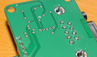
The first step, naturally, is to get Boostbloader downloaded onto the 16f88 on each TDN. You’ll need the little mini adapter from SparkFun in order to reach their mini-ICSP connector. See the 5 holes together in the middle of the board? That's the ICSP "socket". Make sure you work out which way round the connector goes – pin 1 is designated by the square pad. The datasheet shows how this is connected, but it’s a pain having to check the datasheet every time you want to use the ICSP connector. Remember: 1 is square.

Once this is done and you’ve confirmed the Boostbloader is doing its thing by downloading a flashing-led test app of your choice (a see the PicPack demo directory if you’re feeling unadventurous), it’s time to look at the packet demo and how it works. Download the “packet” demo into the 16f88 and get ready for some wireless magic.

The 256 bytes of EEPROM in the 16f88 is a great place for a small amount of persistent data. In this example we use it for storing the address of the node, and the ID of the last packet sent.

In the mini terminal mode, there are several commands that we’ll use to control the node. The first is the “w” command, which allows you to set EEPROM bytes at runtime. The first two digits specify the memory location and the third and fourth digits specify the value you want to set it to. “w0523”, for example, sets EEPROM location 0x05 to the value of 0x23 (all values in hex). In our case, we want to set the address of the node and the last sent packet ID like this:

w0000
w0101
w02ff
w03ff
You only need to do this once. The first two memory locations (00 and 01) store the local address; in this case we’re storing a 16 bit value of 0x0001. The third and fourth EEPROM memory locations hold the ID of the last packet we sent. In a more complete example later on, we’ll see how we update this with the last packet ID over time. For the moment, setting it to 0xffff as we do here is fine. This means the first packet this node sends will have an ID of 0x0000, so this is great for understanding what’s going on.

Set your other node to an address of something else other than 0x0001 (I suggest 0x0002), and also set its last sent packet ID to 0xffff.

Right, so now you have two nodes up and running and ready to communicate. One is set to address 0x0001 and the other is set to 0x0002. You can check that these addresses are stored correctly by resetting the TDN (by pressing the reset button) and seeing the serial terminal program come up with something like:

My addr: 01
Last pkt: 65535
Pkt demo
<17:10:36>
Now it’s time to send a payload from one to the other. Here we’ll send a dummy payload that in future we’ll use to query the temperature on another node. Don’t worry about what’s in the payload for the moment, we’re more interested in seeing a packet make it’s way to the destination and get an acknowledgement back. Go to the terminal connected to your 0x0001 node and type:

s02<enter>
This sets the “send to” (destination) address to 0x0002. This demo is slightly slack by only allowing 8 bit address entry, but I’m sure this won’t bother you with only two nodes right now. This setting of the send address needs to be done whenever you boot.

Now, let’s send a packet. Type:

x<enter>
This should send a packet to the specified destination address (0x0002). Since we only have two nodes right now and hopefully they’re quite close, you should find that node 0x0002 responds pretty much immediately. This is what you should see on the node 0x0001 terminal:

>s02
S: 2
>x
>Send...<Snd good to 0002 id 0000> RX:5
And here’s what you should see on the node 0x0002 terminal:

<<s: 01p: 06 01 FF FF FF FF BF FF >> RX:3
So what’s the deal about these numbers? The demo prints out the return values from the functions that get called. We won’t worry about the functions themselves and what they do right now, but we will look at these values, since they reveal the inner workings of the system. Have a look at pic_packet.h for the #define definitions.

RX:3 - A value of ‘3’ on reception means “PKT_STATUS_PKT_IS_FOR_ME”. It’s a real packet and we haven’t seen it before. We can happily act on this packet. In this demo our “acting” on this packet just involves printing it out to see what we’ve got. You can see the packet was sent from a source address of 01, and had a payload of 06 01 FF FF FF FF BF FF.

RX: 5 - A value of ‘5’ on reception means “PKT_STATUS_PKT_IS_FACK_FOR_ME”. It means we’ve received an acknowledgement and found that it is for a packet we’ve sent. That is, we have successfully confirmed delivery of a packet. Woohoo! We’ve just sent our first packet.

If everything is correct and there are no transmission problems, these are pretty much the only values that you’re going to see with a two-node mesh. Not much of a mesh, really. However, we can simulate what happens in the mesh to help us understand how it works in this simple case. Do note that in this example, the delay between retries has been set deliberately, excruciatingly large so that you can clearly see what’s going on.

Set the sending (destination) address of the 0x0001 node to a node that you know is not on your network (eg, 0x0003) by typing:

s03<enter>
Now from the 0x0001 node try and send a packet to node addressed 0x0003 by typing:

x<enter>
Now, remember from our previous tutorial that we will first try and send to node 0x0003 directly (a “direct send”). You’ll see that node 0x0002 reports a status of PKT_STATUS_DIRECT_SEND (6). This means that it has received the packet, but will not rebroadcast it since the originating node tried to send it directly (no routing).

Since the first packet never got to its destination (an acknowledgement was not received), the node will try to send it again. On the next try however, our node 0x0001 will try and route the packet via anyone that’s listening (a “routed send”). In this simple case, we know that node 0x0002 is listening. Node 0x0002 should respond with PKT_STATUS_NEED_TO_REBROADCAST (9). So 0x0002 rebroadcasts to try and get it to 0x0003 (of course, it doesn’t know that 0x0003 doesn’t exist on our little network).

Now here’s where it gets a bit tricky, but once you’ve got your head around this, you’ll be well on your way to understanding how this all works.

To recap up to this point:

0x0001 has tried to send directly to 0x0003
0x0002 saw it and printed PKT_STATUS_DIRECT_SEND (6) showing that it decided to ignore the packet (it saw that it’s a direct send not destined for itself)
…in time…
0x0001 tried again, this time routing via anyone that’s listening (not a direct send)
0x0002 saw it and responded PKT_STATUS_NEED_TO_REBROADCAST (9), and rebroadcast the packet out to anyone listening (hopefully it can reach 0x0003, or at least someone closer to 0x0003)

Now at this point, 0x0001 should receive this rebroadcast. But it’s the one that sent the packet in the first place! So it should respond with PKT_STATUS_I_AM_SENDER (2) and ignore the packet.

Finally, 0x0001 will give up, printing out

<Send failed to 0003 id 0001>
to show that we’ve had a failed send.

This confirms that 0x0002 has tried to pass the packet on deeper into the mesh, and also confirmed that 0x0001 is happily ignoring this bounce-back. Of course since our imaginary 0x0003 never received the packet, our originating node will try once more. Our plucky little node 0x0002 tries again to forward on into the mesh, but alas, the packet never makes it. If you have no friends, they’re not going to answer, not matter how many times you call.

Clear this is all complete overkill for two nodes (although you do get retries and acknowledged delivery for free). Once you get three or more nodes where some nodes can’t see all the others, I hope you’ll see how powerful this can be for delivering short messages. Next time we’ll have a look at the calls into this library and how they work, finishing our series on the provided packet delivery system works – then later we’ll also cover some implementations of the system, in the first instance delivering temperature data from different nodes.